Carrying Loads in Tension
A wide waterway asks for few obstacles below. A suspended deck answers by sending its weight upward first.
The weight takes a detour
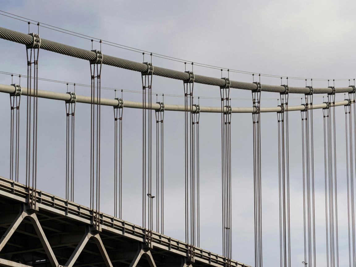
Imagine following one vehicle’s weight through a conventional suspension bridge. The roadway passes the load into the deck’s structural system. Hangers carry it upward to the main cables. Those cables curve over towers and continue toward anchorages. The towers transfer large compressive forces downward, while the anchorages resist the cables’ pull.
That detour makes a long unsupported main span possible. But it also means the bridge depends on a complete system. The dramatic cable curve is only the visible middle of a load path that continues into rock, soil and concrete.
A freely hanging cable cannot resist bending in the way a beam can. It changes shape until its tension balances the applied loads. The deck’s stiffening system helps distribute uneven traffic loads and limits unwanted deformation. Cable geometry and deck stiffness therefore have to be considered together.
Ground conditions are part of the silhouette
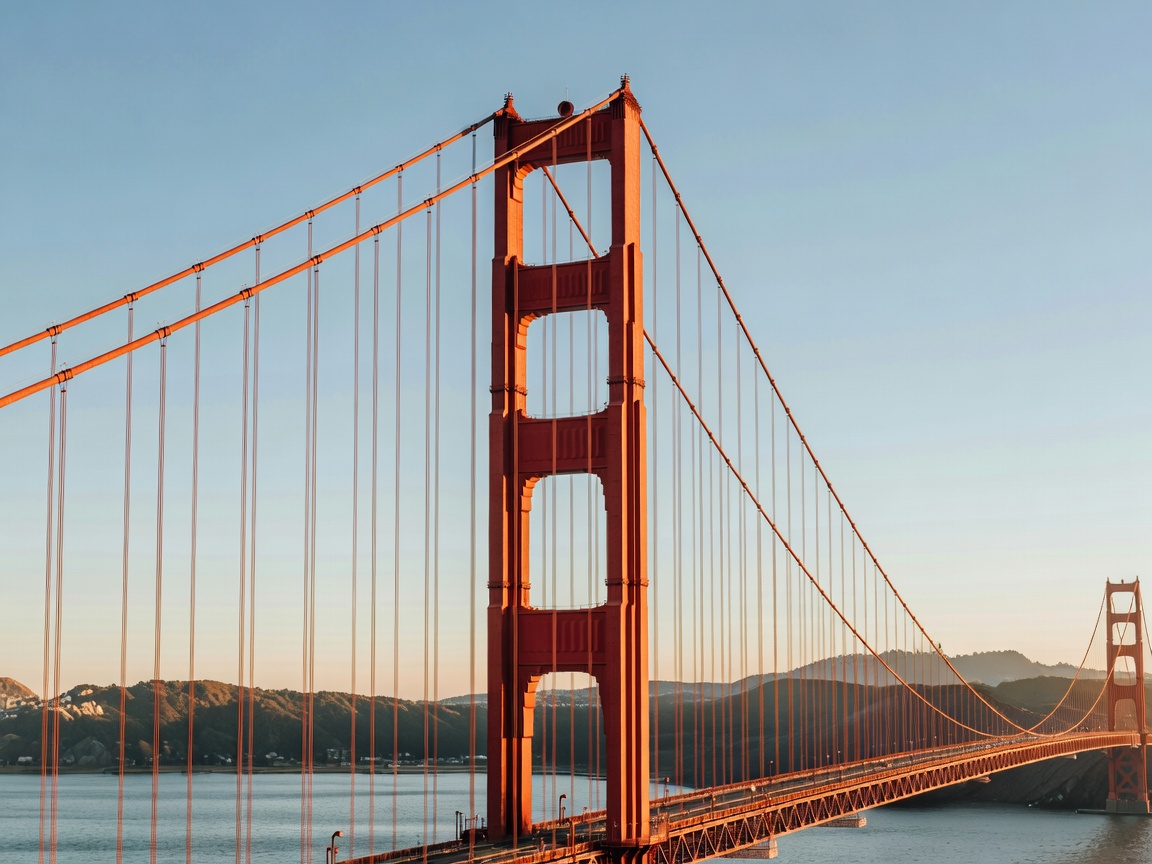
The Golden Gate Bridge crosses a demanding entrance to San Francisco Bay. Its familiar towers and cables belong to a larger arrangement that includes approach structures, anchorages and foundations. Fog may frame the photograph, but geology and exposure help explain the engineering.
Japan’s Akashi Kaikyō Bridge crosses the Akashi Strait between Kobe and Awaji Island. Shipping, strong currents, wind and earthquakes made the site more than a question of distance. Its construction history includes the 1995 Hyōgo-ken Nanbu earthquake, which occurred before the bridge opened in 1998. The lesson is not that any bridge is immune to earthquakes; it is that design and construction have to account for moving ground.
Not every suspended bridge uses huge external ground anchorages. In a self-anchored suspension arrangement, cable forces are returned through the deck. That changes both the permanent load path and the temporary works needed during assembly. A similar outline can therefore conceal a substantially different structural strategy.
Wind is more than a sideways push
A long deck must cope with aerodynamic effects as well as static wind pressure. Moving air can excite motion, and the motion can in turn alter the aerodynamic forces. Engineers investigate this interaction using analysis and wind-tunnel testing, including the behaviour of deck sections and the wider bridge system.
The Tacoma Narrows Bridge collapse in 1940 is often reduced to a simple story about resonance. A more useful introduction recognises aeroelastic instability: interaction between the moving structure and the airflow helped drive destructive twisting. The event changed how engineers understood slender bridge decks. It should not be treated as proof that every flexible bridge is unsafe.
Some movement is normal. Temperature changes alter dimensions; traffic and wind produce deflection. Bearings, joints, stiffness and damping help accommodate or control that movement. Safety is about verified performance within defined conditions, not absolute stillness.
Similar cables, different load paths
A cable-stayed bridge connects the deck directly to towers with inclined stays. It does not use the same continuous main-cable-and-hanger arrangement as a conventional suspension bridge. France’s Millau Viaduct is cable-stayed; the Golden Gate Bridge is suspension. Both use tension in cables, but their deck forces, erection methods and support arrangements differ.
| Bridge | Main span | Opening context |
|---|---|---|
| Golden Gate Bridge | 1,280 m | Opened 1937 |
| Akashi Kaikyō Bridge | 1,991 m | Opened 1998 |
| 1915 Çanakkale Bridge | 2,023 m | Opened 2022 |
A main span is measured between its principal supports. Overall crossing length may include side spans and approaches. The table compares one dimension only; it does not establish which bridge is “greatest,” safest or most difficult to build. Record claims also need a date and a clearly bounded category.
What to notice from a public viewpoint
Look for the curve of the main cable, the direction of the hangers and the depth of the deck. Then locate the towers and imagine where the pull ends on shore. Use designated viewpoints and authorised pedestrian routes. Maintenance areas, anchor chambers and structural members are not visitor access routes.